Before delving into the tutorial, ensure you have the following components and prerequisites in place:
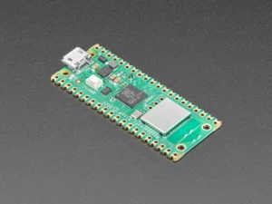
Raspberry Pi Pico W
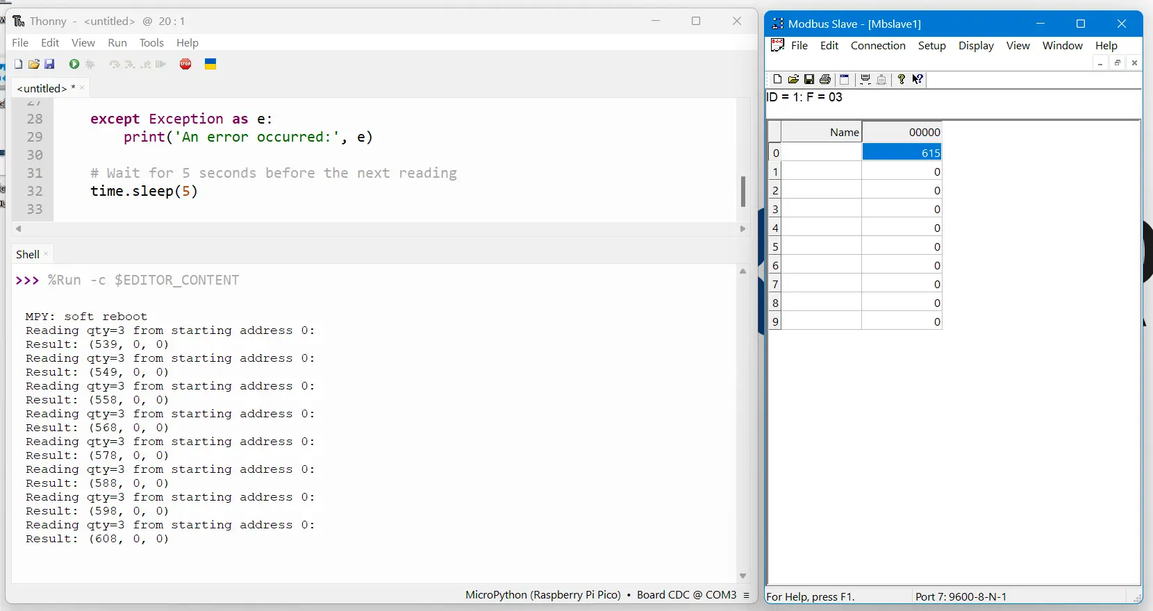
A Modbus slave device or Simulator (e.g., PLC, sensor).
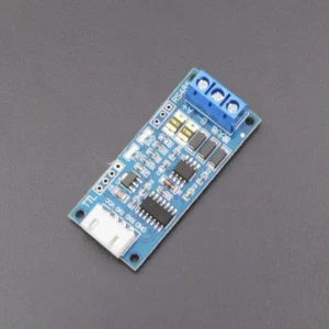
TTL to RS485 converter.
MicroUSB cable for Pico.
A computer with Thonny or another MicroPython IDE installed.
Basic knowledge of Python and Modbus protocol.
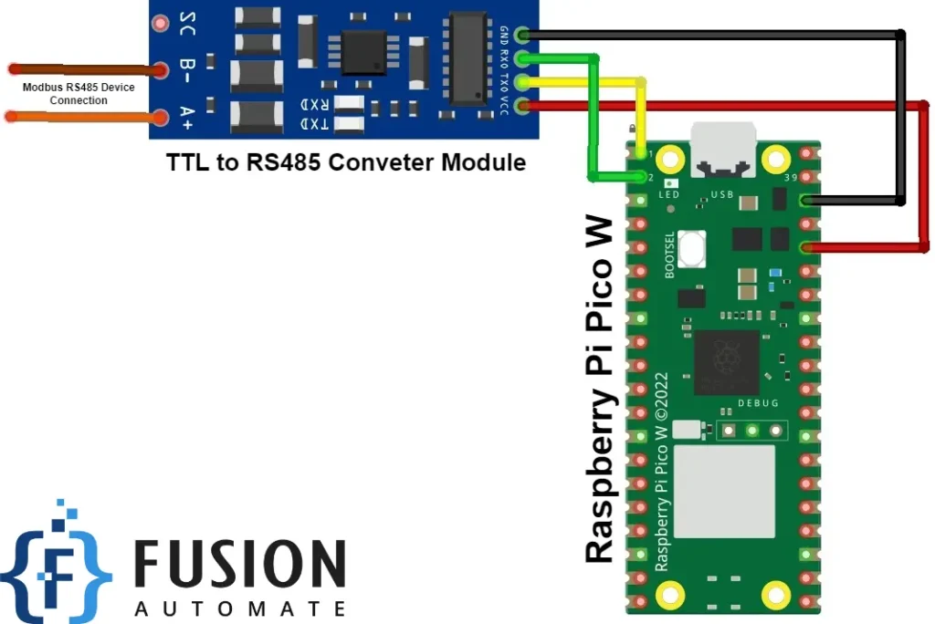
Setting up the hardware involves establishing connections between Raspberry Pi Pico W, TTL to RS485 converter, and the Modbus slave device: